how to win at riverslot sweepstakes internet cafe
i want to fuck my coworker whisper
young looking giel braces fuck
big bang theory sweepstakes
sex and the menopause uk
warframe argon scope drop
how to recognize a legitimate sweepstakes
wew.google .com
how to replace welded door hinges on chevy silverado
toronto sex partner
In the world of automotive performance, there are many ways to enhance the power and efficiency of a vehicle. One popular method is by installing an innovative performance chip. These chips are designed to optimize the engines performance by adjusting various settings and parameters. In order to properly install and utilize a performance chip, it is important to have a thorough understanding of the wiring diagram. A wiring diagram is a visual representation of the electrical system of a vehicle. It shows the various components and how they are connected to each other. For the installation of an innovative performance chip, the wiring diagram is essential. It provides a roadmap for connecting the chip to the vehicles electrical system. The innovative performance chip wiring diagram typically consists of several components. These include the power source, ground connection, sensor inputs, and output connections. The power source is usually connected to the vehicles battery, providing the necessary voltage for the chip to operate. The ground connection ensures that the chip has a solid electrical reference point. Sensor inputs are used to gather data from the vehicles various sensors, such as the mass airflow sensor or engine temperature sensor. Finally, the output connections are used to send signals back to the vehicles engine control unit (ECU) to make adjustments based on the chips programming. When installing an innovative performance chip, it is crucial to follow the wiring diagram carefully. Each wire must be connected to the correct terminal or pin on the chip and the vehicles electrical system. Failure to do so can result in improper operation or even damage to the chip or other components. In addition to the correct wiring, it is also important to ensure that the correct chip is selected for the vehicle. Different vehicles and engines require different performance chips, so it is crucial to choose the right one for optimal results. It is recommended to consult with a knowledgeable professional or refer to the manufacturers guidelines to select the appropriate chip for your specific vehicle. Once the correct chip has been selected and the wiring diagram has been studied, the installation process can begin. This typically involves locating the appropriate wires and terminals on the vehicles electrical system and making the necessary connections. It is important to double-check each connection to ensure it is secure and properly connected. After the chip has been installed and the wiring connections have been made, it is important to test the system to ensure it is functioning correctly. This can be done by starting the vehicle and monitoring its performance. The chip should make noticeable improvements in power, fuel efficiency, and overall performance. If any issues arise, it may be necessary to double-check the wiring connections or consult with a professional for further assistance. In conclusion, an innovative performance chip is a valuable tool for enhancing the power and efficiency of a vehicle. However, in order to properly install and utilize the chip, it is important to have a thorough understanding of the wiring diagram. The diagram provides a roadmap for connecting the chip to the vehicles electrical system, ensuring that the chip operates correctly. By following the wiring diagram carefully and selecting the appropriate chip for the vehicle, drivers can enjoy the benefits of improved performance and efficiency.
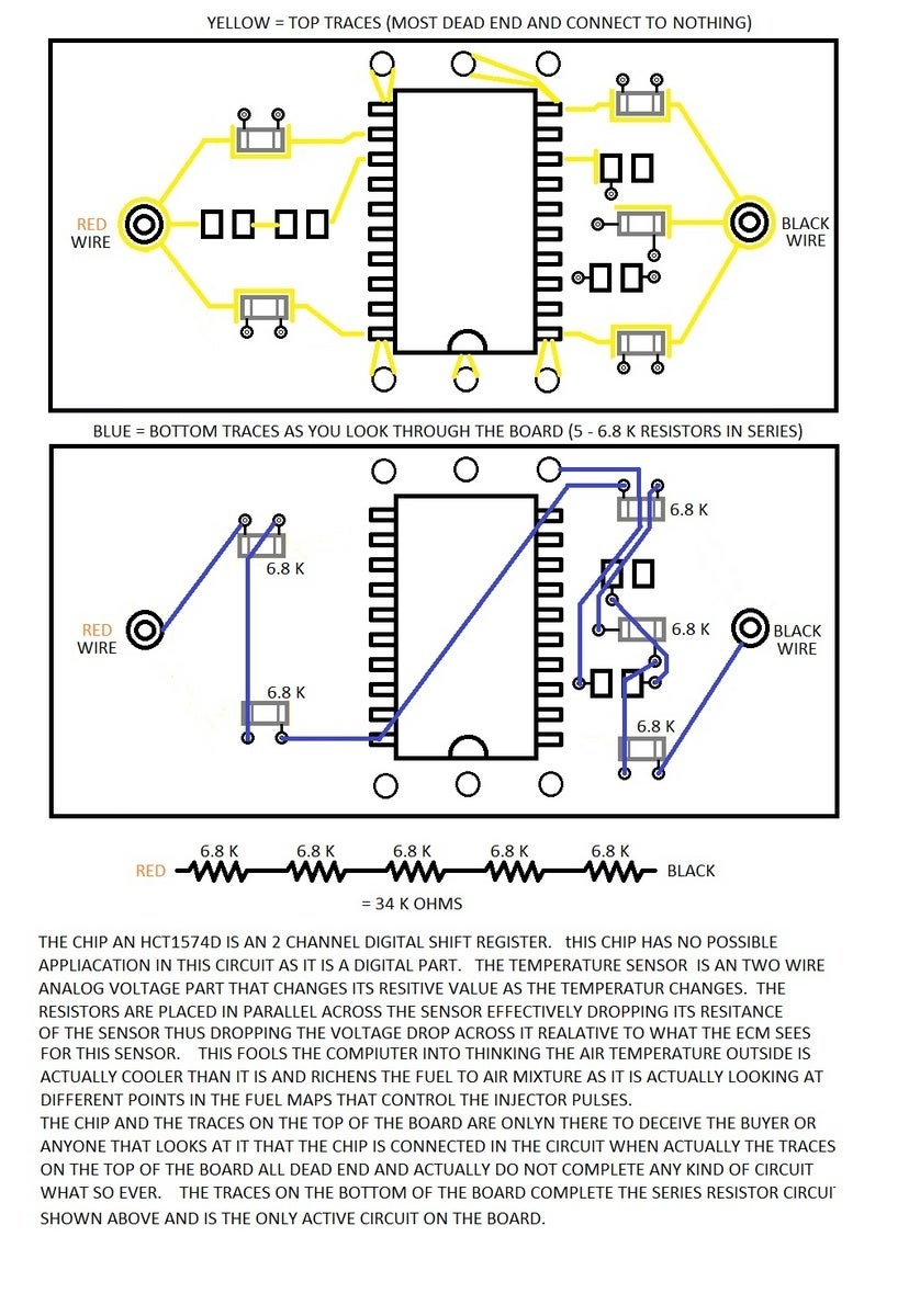
Innovative Chip Installation & Instructions . I ordered an Innovative Performance Chip off Amazon for $70 and Im installing it here. Not 100% sure if it works or not but will soon do an after video in about a week to post after chip .. Innovative Performance Chip Install Pt. 1! innovative performance chip wiring diagram. 126K views 6 years ago innovative performance chip wiring diagram. Please like and subscribe to see part 2 of this install and some 0-60 times!!! This was the first part of the Innovative performance chip on my 2006 Chevy Colorado! Show. innovative performance chip wiring diagram. Tag: INNOVATIVE PERFORMANCE CHIP INSTALLATION INSTRUCTIONS. Innovative-Performance-Chip-OBD-Top-PCB-Fake-Connection-Traces. If we turn the board over, we see more unsoldered connections, essentially the same as the top - only two pins from the chip are even connected. innovative performance chip wiring diagram. The chip contains 8 isolated resistors as shown in the lower diagram above. The left two pins, 1 and 14, are the first 38K .. How To Install a Performance Chip - Dr Performance RX. Here are step-by-step instructions on how to install one of Dr. Performances performance chips on your Dodge Ram Cummins or Ford Powerstroke. Do you learn better through visuals? You can check out our module install videos instead.. Performance Chip Information And Installation (OBD 1) . In this episode, we show you how to install a performance chip in your fuel injected vehicle innovative performance chip wiring diagram. You can now get your very own budget boosting window sticker! Click the link below and you will be .. Tag: INNOVATIVE PERFORMANCE CHIP WIRING DIAGRAM. This is a review and analysis of the Innovative performance chip module innovative performance chip wiring diagram. If you are looking for a REAL Innovative performance chip review, then this is for you! What is this product and what does it do? Lets take a closer look: Company Profile… Continue readinghow to win at riverslot sweepstakes internet cafe
. Innovative Performance Chips. Boost your fuel economy, horsepower, torque and throttle response with the advanced Innovative Performance Chip! Safely gain up to 35 HP and up to 5 MPG in fuel mileage by safely optimizing your engine for increased efficiency! SHOP NOW. Engineered & assembled in the U.S.A. of U.S innovative performance chip wiring diagrami want to fuck my coworker whisper
. & imported parts.
young looking giel braces fuck
. LOCATE the OBD-2 PORT under the driver-side dashboard innovative performance chip wiring diagram. 3 innovative performance chip wiring diagram. CHECK THE OBD2 PORT for any dirt, dust, or grimebig bang theory sweepstakes
sex and the menopause uk
. Locate your air intake box and prepare for removalwarframe argon scope drop
. The Tunesport Performance Chip is the answer to increasing performance and .. Innovative Performance Chip Wiring Diagram. Web Innovative Performance Chip Wiring Diagram innovative performance chip wiring diagram. Web the process of chip manufacturing is like building a house with building blocks. You will also have access to all the wiring diagrams, latest firmware, software and manuals.. IBM100 - Copper Interconnects: The Evolution of Microprocessors. Copper in chips innovative performance chip wiring diagram. Replacing aluminum wiring in chips had been thought by most to be impossible, for a number of technical reasons innovative performance chip wiring diagram. However, an IBM team overcame those technical problems, bringing copper wires into production quickly, giving an immediate boost to chip performance.. Tag: INNOVATIVE PERFORMANCE CHIP WIRING DIAGRAM. The only two connections to the chip are the top left and bottom left (see photo below): Innovative-Performance-Chip-OBD-Top-PCB-Fake-Connection-Traces innovative performance chip wiring diagram. If we turn the board over, we see more unsoldered connections, essentially the same as the top - only two pins from the chip are even connected. innovative performance chip wiring diagram. Innovative Performance Chip Review - Car Performance Chip Reviews. The only two connections to the chip are the top left and bottom left (see photo below): Innovative-Performance-Chip-OBD-Top-PCB-Fake-Connection-Traces
how to recognize a legitimate sweepstakes
. 11. Reconnect the batteries and start the truck. 12. If the truck fails to start, remove the computer again and try . innovative performance chip wiring diagram. Innovative Performance Chip - YouTube innovative performance chip wiring diagram. Innovative Performance Chip TOUGHBUILDS CUSTOMS 1.29K subscribers Subscribe 569 92K views 5 years ago #summary #of #this #video ------------------------------------------- This Innovative.. What to wires to use. On my ford f250 to hook my innovative performance .. SOURCE: installing chip and want to double check wiring. Need to find IAT/MAF sensor diagram for 2003 Ford Ranger. Save your money, the chip is a ohm resistor at Radio Shack for under $2.00. It splices in to you IAT wire harness located at the intake tube between the air filter housing and throttle body.. Installation Guides - Edge Products. Revolver Performance Chip/Switch Ford 7.3L 2001 Manual 6-Chip Master Box Code Apx1. Part Number 14008 - Install Instructions. Revolver Performance Chip/Switch Ford 7.3L 02-03 Auto 6-Chip Master Box Code Vdh4. Part Number 14009 - Install Instructions.. PDF MTX-L Digital Air/Fuel Ratio Gauge User Manual - Innovate Motorsports. 2.1 Wiring The MTX-L has 5 stripped wire ends: Connect the RED wire to an isolated switched 12V source in your vehicle. A switched 12V source goes ON as soon as "key on" power is active. The circuit to which you will pull power from should be able to support a 3 amp draw. Make sure this connection is protected with a 5A fuse. innovative performance chip wiring diagram. QG18 ecu wiring diagram | Nissan Forum. Straight-4 QG18 1.8L Engine QG18 ecu wiring diagram 11360 Views 4 Replies 4 Participants Last post by dschrier , Jun 25, 2004 B Black_Dragon Discussion Starter · Jun 24, 2004 Hey guys, Does anyone have or know where I can get the wiring diagrams needed to install a Unichip? I asked Unichip already but they sent the diagram for the QR25 . innovative performance chip wiring diagram. SOLVED: Installing chip and want to double check wiring. - Fixya. 1 Answer Installing chip and want to double check wiring. Need to find IAT/MAF sensor diagram for 2003 Ford Ranger Need IAT/MAF Sensor diagram for 2003 Ford Ranger innovative performance chip wiring diagram. Trying to install SLR performance chip and want to be sure I have correct wiring. Posted by sfreemen on May 29, 2009 Want Answer 0. To Install My Vertex Performance Chip. Should I Use the - JustAnswer. Technician. Associate Degree. 19,160 satisfied customers. Chevrolet Silverado 1500 Classic WT: I have a Gforce performance. I have a Gforce performance chip and want to install it on my 2012 chevrolet silverado 1500 with V6 and would appreciate your help Rick …. innovative performance chip wiring diagram

wew.google .com
. f150 IM trying to hook up a gforce chip to my 2011 f150 with from www.justanswer.com Fordson super major wiring diagram; Open up the glove compartment and unscrew the screws that hold the panel in place.. Wiring a GForce performance chip and dont know which two . - JustAnswer innovative performance chip wiring diagram. Wiring a GForce performance chip and dont know which two wires to use on a 2004 BMW X5 3.0i. Submitted: 12 years ago. Category: BMW. Show More. Show Less. Ask Your Own BMW Question. Share this conversationhow to replace welded door hinges on chevy silverado
. . 2008 535i: chipdiagramengine compartment on the passenger side.. SOLVED: Im installing a GForce Performance Chip but im - Fixya. 1 Answer Anonymous Contributor 18 Answers Im installing a Gforce chip and I do know were the IATMAF sensor is located, but I still can not figure out which 2 wires I need to connect it to? I have the 5 wire sensor which ones do i need to hook up too. I do not get any reading on my multimetertoronto sex partner
. And yes the battery is connected.. Need IAT/MAF wiring diagram for a 2008 5.7 liter Toyota Tundra. 1 Answer Need IAT/MAF wiring diagram for a 2008 5.7 liter Toyota Tundra Want to connect a G Force Performance chip but cant locate a IAT/MAF wiring diagram to follow. Posted by jstroxel on Jul 02, 2012 Want Answer 0 Clicking this will make more experts see the question and we will remind you when it gets answered